Electrical Engineering Examples
Aerospace & Aviation
This science instrument was developed for a NASA AMES project to measure and quantify the number and type of energy particles astronauts are exposed to in space environments. Initially slated for the lab on the International Space Station, our client was responsible for developing instrument mechanicals, electronics and build.
This meant meeting all of the aerospace requirements… including shock & vibration, heat dissipation, radiation hardened components as well as redundancy built into the firmware in order to meet reliability requirements and protect against radiation induced latch up in the electronics.

Instrumentation Electronics
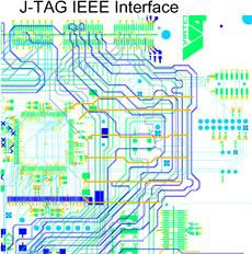
Each of the instrument’s electronic component categories were selected for radiation hardness and then further evaluated for appropriateness utilizing Kepner Tregoe Analysis methodologies. We then integrated the prototype commercial microprocessor into the selected radiation-hardened FPGA and implemented triple modular redundancy (TMR) and instantiated the processor.
Heat Management Shock & Vibe
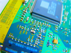
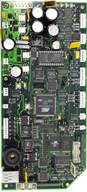
Advantage designed the printed circuit board specifically to carry heat away from the electronic components into the aluminum enclosure to manage the difficulty of heat dissipation in a zero-gravity environment.
This meant meeting all of the aerospace requirements… including shock & vibration, heat dissipation, radiation hardened components as well as redundancy built into the firmware in order to meet reliability requirements and protect against radiation induced latch up in the electronics.

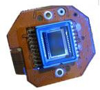
As part of the navigation system of a spacecraft, Star Tracker Cameras use the stars as reference points comparing what is imaged to a stored software catalog of stars located on the spacecraft’s processor. It collects a picture of the star field around the spacecraft and performs a 3-axis attitude determination using an algorithm that compares the relationships of stars to the craft.
The Advantage team designed a miniaturized Star Tracker Camera with a Scientific Imaging Technologies CCD (512 x 512 parallel array, 24µ x 24µ, 12.3 mm x 12.3 mm imaging area). This camera has a large dynamic range and high sensitivity. It utilizes a patented cooling technology reducing size, weight and cost of an imaging system.
A compact, low mass star tracker camera is ideal for small satellites such as nanosats and microsats which are the trend for both Government and commercial programs.
Advantage has experience with three of the systems of a spacecraft bus; the Command & Data Handling Unit (C&DH), the Attitude Control System (ACS) and the Thermal Control Subsystem. Additionally, we have performed flight board design, participated in IR&D and other emerging technology efforts (ie: nanosat miniaturized avionics with Rad Hard PPC750 Processor) with Industry Partners as well as developed a proprietary Single Event Upset (SEU) scrubbing, detection and management system at the processor level.
As of 2019 there are 14 orbiting satellites we have contributed to:
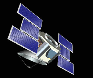
Quickbird
In November of 2000, EarthWatch (now DigitalGlobe) launched the QuickBird 1 satellite from the Plesetsk cosmodrome in Russia but it failed to reach orbit. A successful launch of QuickBird 2 (QuickBird) ensued on October 18 of 2001.
QuickBird is the first in what will by 2008, be a constellation of commercial imaging satellites. The constellation will enable commercial and government customers to access broad selection imagery.
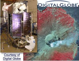
DigitalGlobe intends to assemble a multi-source digital archive of spatial data that provides customers access to up-to-date earth information and the QuickBird satellite is currently the only commercial spacecraft able to offer sub-meter resolution imagery, industry-leading geolocational accuracy, large on-board data storage, and an imaging footprint two to 10 times larger than any other commercial high-resolution satellite. It is designed to support applications ranging from map publishing and land management to asset monitoring and emergency response planning.
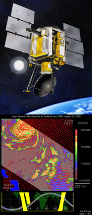
QuickSCAT SeaWinds

NASA’s Quick Scatterometer (QuikSCAT) satellite was launched June 19, 1999, on a Titan II rocket from California’s Vandenberg Air Force Base. It circles Earth at an altitude of 800 kilometers (500 miles) once every 101 minutes, passing close to Earth’s north and south poles.
The scatterometer SeaWinds instrument on the QuikSCAT satellite is a specialized microwave radar that measures near-surface wind speed and direction under all weather and cloud conditions over Earth’s oceans.
Scatterometers operate by sending radar pulses to the ocean surface and measuring the “backscattered” or echoed radar pulses bounced back to the satellite. The instrument senses ripples caused by winds near the ocean’s surface, from which scientists can compute the winds’ speed and direction. Used for weather forecasting and long-term climate studies, QuikSCAT‘s measurements also provide an early look at developing hurricanes.
The mission is managed by JPL, which also built the Seawinds radar instrument. NASA’s Goddard Space Flight Center managed development of the satellite, designed and built by Ball Aerospace & Technologies Corp.
CloudSat - Launch Success!
Launch of CloudSat/CALIPSO successfully occurred on Friday morning, 28 April 2006 on the sixth attempt. At approx. 6:02 a.m. EDT, the Boeing Delta II rocket carrying the CALIPSO and CloudSat satellites soared into space from the California coastline.
Sixty-two minutes after liftoff, Calipso separated from the rocket’s second stage. CloudSat followed 35 minutes later. Ground controllers successfully acquired signals from both spacecraft, and initial telemetry reports show both to be in excellent health. Over the next six weeks, system and instrument checks will be performed, and the satellites will be inserted into their final orbits.
CloudSat is an experimental satellite that will use radar to study clouds and precipitation from space. CloudSat will fly in orbital formation as part of the A-Train constellation of satellites.
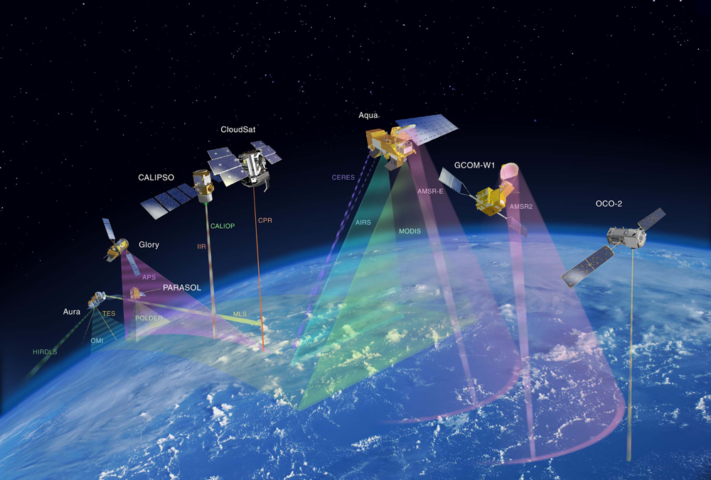
CloudSat is managed by NASA’s Jet Propulsion Laboratory. JPL also developed the radar instrument with hardware contributions from the Canadian Space Agency. Colorado State University provides scientific leadership and science data processing and distribution. Ball Aerospace and Technologies Corp., Boulder, Colo., designed and built the spacecraft. The U.S. Air Force and U.S. Department of Energy contributed resources. U.S. and international universities and research centers support the mission science team.
Green
Two University Studies have conclusively demonstrated that the heat from the windows does not radiate to the outside of the building.

Several hundred of the windows were installed in a Platinum rated LEEDs building, the Golisano Library in Rochester New York.
For this project, our client asked us to developed windows of various sizes with the ability to heat up to 140 degrees when power is applied to them. We developed a controller to regulate the window temperature and smartphone applications for both Android and Apple to give the user configuration control and access to diagnostic information (such as error or fault conditions) through these applications.

Product Features
The controller supplies 110VAC that is present in residential and commercial buildings to the radiant heating elements of the window. Each controller provides control for up to 3 heated windows in a set. The user has the ability to individually configure each of these windows to a specified temperature through the custom Smart Phone application.
Built into the system are several safety features including automatic shutoff of power to each window in the event of breakage or any other fault or error condition. If one of these events occurs the embedded controller automatically shuts off power to each window and provides an error message representing the fault condition via either a visual indication at the controller or through the custom Smart Phone application.
The controller is designed to fit into a standard construction box which can be easily and discretely mounted out of sight such as in a wall between studs, a breaker room or within the hanging ceiling of a commercial building.
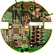
Wireless Smart Home Device
- Zigbee RF network chipset for local and remote units.
- PIC 18F series microcontroller
- Multiple analog and digital sensors
- Modem with line interrupt relay. Dual line configurable.
- Status LEDs
- 16 character LCD for user interface
- 100 db alarm sounder
- Battery backup
- Up to 10 individual sensors can be networked
- 100 ft range*
- Automatic RF authentication, connect, disconnect, polling and re-transmit
- Cascading alarm reporting, multiple reporting hosts
- Test and Mute modes
- Configurable alarms and status reporting, multiple alarm tracking
- Dial-up remote configuration programming
- Dial-up remote system control
Our engineering team designed, tested and debugged the hardware and software using leading Zigbee pre-production products. This product posed a significant engineering challenge because much of the design and testing effort was conducted while Zigbee part specs and protocols were still being developed.
*Maximum range depends on several factors including building environment and RF interference.
Coming Soon....
Environmental Analytical Instruments
Water Pollution Monitoring and Abatement
Design for cost reduction
Original design
- Reduction in total number of different components used, resulting in higher volumes for each and less effort in sourcing and maintaining the bill of materials.
- Conversion of the older thru-hole designs to surface mount, CE compliantcomponents resulting in significantly decreased manufacturing costs for all 6 independent instruments.
- The customer’s product support team now has fewer hardware designs to support.

Medical
Smart Prosthetic Controlled by iPad, iPod & iPhone
Our clients, innovators with a disruptive medical product concept had deep clinical experience but no product development experience. They engaged our services to flesh-out their idea and develop their system from end to end as well as to protect their concept, and take it through complicated regulatory testing then manufacture and get it out to the market.
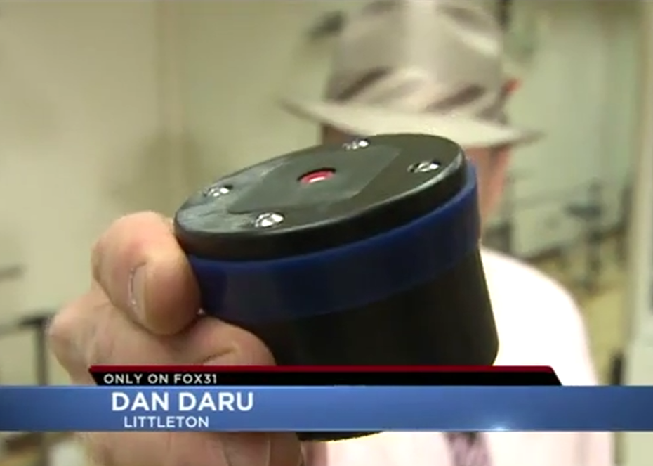
Check out Fox 31’s news story on how Advantage’s mhealth solutions are allowing amputees to take control of their prosthetics.
Smart Prosthetic Controlled by iPad, iPod & iPhone
Our clients, innovators with a disruptive medical product concept had deep clinical experience but no product development experience. They engaged our services to flesh-out their idea and develop their system from end to end as well as to protect their concept, and take it through complicated regulatory testing then manufacture and get it out to the market.
Check out Fox 31’s news story on how Advantage’s mhealth solutions are allowing amputees to take control of their prosthetics.
Utilities
Wireless Smart Home Device
- Zigbee RF network chipset for local and remote units.
- PIC 18F series microcontroller
- Multiple analog and digital sensors
- Modem with line interrupt relay. Dual line configurable.
- Status LEDs
- 16 character LCD for user interface
- 100 db alarm sounder
- Battery backup
- Up to 10 individual sensors can be networked
- 100 ft range*
- Automatic RF authentication, connect, disconnect, polling and re-transmit
- Cascading alarm reporting, multiple reporting hosts
- Test and Mute modes
- Configurable alarms and status reporting, multiple alarm tracking
- Dial-up remote configuration programming
- Dial-up remote system control
*Maximum range depends on several factors including building environment and RF interference.
Green Technology Developments - Heated Windows
Imaging
Designed utilizing Texas Instrument’s TMS320DM310 CCD controller/video DSP chip, TI’s TMS320LF2407 DSP microprocessor and TI’s TRF6900 single chip UHF 850UUHF 830-950Mhz RF transceiver. This camera also incorporated a TLV320AIC23 stereo audio codec, LV4135W LCD controller, flash ram, USB and RS232.
TMS320DM310:
- Real-time MPEG-1, -4 encode at CIF resolution (352 x 288)
- Real-time MPEG-4, video decode at VGA resolution (640 x 480)
- One-second shot-to-shot delay for 6-megapixel image
- Supports multiple applications and file formats, including AAC, H.263, H.265, JPEG, JPEG2K, M-JPEG, MP3, MPEG-4, MPEG-2, MPEG-1, WMA and WMV
- Highly integrated system-on-a-chip (SoC) design reduces overall system cost
TMS320LF2407:
- 16-bit fixed point DSP with Flash
- Low-Power 3.3-V design
- Two Event-Manager (EV) Modules (EVA and EVB), Each Include:
- Two 16-Bit General-Purpose Timers
- Eight 16-Bit Pulse-Width Modulation (PWM) Channels Which Enable:
- Three-Phase Inverter Control
- Center- or Edge-Alignment of PWM Channels
- Emergency PWM Channel Shutdown With External PDPINTx\ Pin
- Programmable Deadband (Deadtime) Prevents Shoot-Thorough Faults
- Three Capture Units For Time-Stamping of External Events
- On-Chip Position Encoder Interface Circuitry
- Synchronized Analog-to-Digital Conversion
- 10-Bit Analog-to-Digital Converter (ADC)
- 8 or 16 Multiplexed Input Channels
- Selectable Twin 8-input Sequencers Triggered by Two Event Managers
- Controller Area Network (CAN) 2.0B Module
- Serial Communications Interface (SCI)
- 16-Bit Serial Peripheral Interface (SPI) Module
- Phase-Locked-Loop (PLL)-Based Clock Generation
- Up to 40 Individually Programmable, Multiplexed General-Purpose Input/Output (GPIO) Pins
- Up to Five External Interrupts (Power Drive Protection, Reset, and Two Maskable Interrupts)
TRF6900A:
- TRF6900 single-chip UHF transceiver · 850-950 MHz operating range
- FSK operating mode
- Low power consumption due to ultra-fast turn-off/turn-on times
- On-chip DDS synthesizer, VCO and reference oscillator enables channelized systems
- MSP430 ultra-low-power microcontroller
- Ultra-low power consumption (350 μA active, 1.3 μA standby, 0.1 μA shutdown mode)
- High throughput 16-bit RISC architecture with up to 5 MIPS
As part of the navigation system of a spacecraft, Star Tracker Cameras use the stars as reference points comparing what is imaged to a stored software catalog of stars located on the spacecraft’s processor. It collects a picture of the star field around the spacecraft and performs a 3-axis attitude determination using an algorithm that compares the relationships of stars to the craft.
The Advantage team designed a miniaturized Star Tracker Camera with a Scientific Imaging Technologies CCD (512 x 512 parallel array, 24µ x 24µ, 12.3 mm x 12.3 mm imaging area). This camera has a large dynamic range and high sensitivity. It utilizes a patented cooling technology reducing size, weight and cost of an imaging system.
A compact, low mass star tracker camera is ideal for small satellites such as nanosats and microsats which are the trend for both Government and commercial programs.
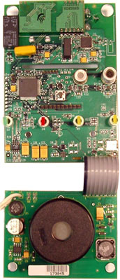
Wireless
Wireless Smart Home Device
This wireless sensor network smart home device was designed with plug and play installation capability. It is based on cutting edge wireless technology and scheduled to be installed in millions of homes nationwide. All product configuration is done remotely by the host and in-home installation does not require re-wiring.
Hardware features included:
- ZigBee RF network chipset for local and remote units.
- PIC 18F series microcontroller
- Multiple analog and digital sensors
- Modem with line interrupt relay. Dual line configurable.
- Status LEDs
- 16 character LCD for user interface
- 100 db alarm sounder
- Battery backup
- Up to 10 individual sensors can be networked
- 100 ft range*
Software features included:
- Automatic RF authentication, connect, disconnect, polling and re-transmit
- Cascading alarm reporting, multiple reporting hosts
- Test and Mute modes
- Configurable alarms and status reporting, multiple alarm tracking
- Dial-up remote configuration programming
- Dial-up remote system control
Our engineering team designed, tested and debugged the hardware and software using leading Zigbee pre-production products. This product posed a significant engineering challenge because much of the design and testing effort was conducted while Zigbee part specs and protocols were still being developed.
Maximum range depends on several factors including building environment and RF interference.
Medical Devices
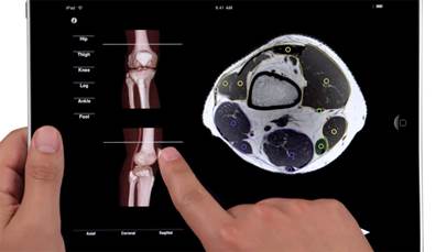
Smart Prosthetic Controlled by iPad, iPod & iPhone
Our clients, innovators with a disruptive medical product concept had deep clinical experience but no product development experience. They engaged our services to flesh-out their idea and develop their system from end to end as well as to protect their concept, and take it through complicated regulatory testing then manufacture and get it out to the market.
Their life-changing idea minimized the size, weight and complexity of prosthetics while adding the intelligence and means to control its settings by using a smart phone (which many of its end users already owned) and making it in such a way that that intelligence that that intelligence can be moved forward to the user’s next socket. This technology gives the prosthetist the means to record the usage and other information required for reimbursement of the device, as well as real time information about what is going on in the prosthetic socket (the plastic shell the residual limb fits into) as the wearer performs various activities.
The Smart Phone as a remote control allows the user to interact with a graphical interface they are familiar with, avoid the expense and bother of another wireless device and spares any awkwardness the user might experience in explaining what a separate remote is for. It is one less thing to have to carry around.
Check out Fox 31’s news story on how Advantage’s mhealth solutions are allowing amputees to take control of their prosthetics.
Additional Projects
The maritime navigator computer was designed for a client that is a software developer with strategic relationships with satellite resources for link data and GPS positioning information. They enlisted us to develop a product vehicle to market their navigation related software to aircraft and watercraft owners.
The client had already decided upon the OS and Application software that was to run on the system, designed a case to fit a selected LCD screen and so forth. Our task was to take what they had previously determined and expand on it to meet their needs.
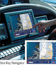
A system was designed around a single board computer expanding it’s capabilities by adding several kinds of interfaces. These interfaces included: USB expansion –expanding into 4 USB ports adding 4 more serial ports to the 2 existing serial ports; an embedded touch- screen controller to interface between the touch-screen overlay and the CPU via a USB channel; an Ethernet port with the addition of the isolation / impedance matching transformer and status indicators; and an interface to an embedded IDE disk drive.
Other I/O included VGA signal conditioning (filtering for EMI) and a membrane keypad. The LCD screen was lighted with an integrated backlight circuit with brightness control. The membrane keypad was backlit with an electroluminescent panel. USB, Serial RS-232 and Ethernet port connectors were placed to allow connection to the backside or side of the unit as needed by the end user. An 8 bit parallel port and stereo audio were also part of the system.
The hardware design effort required interfacing with the customers’ software engineers to ensure that the added interfaces would be compatible with the OS as well as their application software, and would handle the I/O timing requirements.
We designed a prototype and worked with the customer at an EMI/EMC testing facility in order to allow it to meet all FCC EMI/EMC requirements by working out what shielding was needed where, and any redesign that may be necessary. This resulted in re-working the LCD cabling and redesigning the LCD drive circuitry to utilize LVDS (Low Voltage Digital Signaling).
Following this effort, we built the field test units, and supported the customer through field testing and into production.
Our clients come to us with varying needs and requests. One recent customer had been trying for two years to upgrade their existing sports timing product. The marketing staff wanted newer, more competitive features. The controller wanted a product that had enough pricing room to make adequate profit. The sales staff wanted a product that could be sold in any country and meet its regulatory requirements.
The project objectives were to achieve at least a 30% cost improvement using parts that had at minimum 5-year life. It was important that we convert to different parts for the cost advantage and lead free components to meet regulatory requirements.
The existing product used an embedded PC with dedicated PC 104 interface for timing functions. This style of embedded PC can be expensive and does not ride the declining price curve like PC’s that are meant for consumer products. By switching to a single-board, consumer PC, we saved about 50% of the cost of the processor. Instead of using a dedicated bus interface, we determined that there was adequate bandwidth on a standard RS-232 serial interface. This would give the client flexibility to use our timer board in other applications as well as cost less to implement.
The existing product had many cables connecting the various boards. By going to a single board with all non-host functions on it, we saved the cost of the cables, the labor required to connect the boards and the resulting reliability issues inherent with using connectors in a rugged outdoor environment.
The client ‘s existing product used RS-232 serial communications to their scoreboard, which was not appropriate for the data rate they desired. Consequently, we changed to RS-485 differential signals to avoid interference and achieve the data rate they were looking for.
Because of our experience with product development and packaging, we recommended a change to the packaging strategy. This saved significant percentage of the target cost-reduction and they began shipping their existing product in this manner, prior to the new product introduction.
On the timer board we used a Microchip PIC18 processor for command processing, queue management and time measurement and a Xilinx FPGA to interface to the various switches used for timing, condition and debounce them.
Advantage achieved the desired 30% cost reduction, expanded product functionality and reliability while still maintaining compatibility with the bulk of the customer ‘s legacy sport ‘s management software.
Advantage has remained at the forefront of technology with the development of a variety of FPGA and ASIC development/emulation platforms. These development environments are high speed signal designs such as PCIe and SAS/SATA interfaces utilizing SERDES (Serializer/ Deserializer) techniques as well as DDR interfaces. With the high speeds of these designs (many 3.5Gbs and higher) signal integrity analysis is required to ensure a viable product.
When driving high speed signals through “Large Scale” devices such as FPGA’s, the design and layout becomes an exacting discipline.
The clocks (and usually data paths) must be differentially driven with matched length using impedance controlled circuit traces. Devices with internal clock multipliers/dividers need low ‘jitter’ clock sources with appropriate PCB layout to minimize reflections or losses that can keep a design from working properly. The power distribution system (PDS) must be carefully considered to maintain clean power to all power and ground connections to these active devices and power/ground planes must be properly placed and configured. The voltage keeps going lower and the current keeps going higher as the speeds of today’s designs ever increase. This adds the complexity of having local voltage regulators (and usually several voltage levels) placed near the high speed parts. These regulators generate heat that must be dealt with, and the regulators ability to supply clean power must be carefully considered.